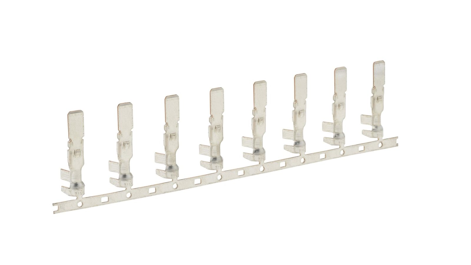
Clad Metal Stamping — ±0.005 mm on 0.05–3.0 mm clad strip, up to 300 SPM
Progressive die stamping of clad, inlay and overlay strip: silver on copper contact faces, copper on steel busbars, copper-aluminum transition joints. Dies are built in our own tool room, run on 21 presses from 25 to 110 tons at up to 300 SPM, with the bond line oriented against the bend at DFM.
0.05–3.0 mm clad strip
±0.005 mm positional
up to 300 SPM
21 presses · 25–110 T
Fast Engineering ResponseNDA ProtectedSTEP / IGES / X_T / DWG
Clad work is chosen when one metal cannot do the whole job: conductivity at the contact, weight or cost in the body. These four families carry most of the clad strip that runs here, and each one is a different bond-orientation problem.
Silver and gold inlay contacts
Relay, switch and connector contacts where the precious metal sits only where the arc lands. An inlay stripe runs down the carrier, and the die blanks the inlay inside the contact dome so the silver footprint matches the mating face instead of the whole part. Blanking, forming and inlay alignment happen in one progressive pass.
Ag / Au inlay0.1–0.8 mmrelay & switchcopper carrier
Copper-aluminum transition joints
Battery interconnects, busbar tabs and terminal pads that join aluminum to copper without a bolted interface. Roll-bonded Cu-Al strip puts the metallurgical joint inside the part, so the assembly loses a dissimilar-metal fastener and the galvanic couple moves to a bond line we can inspect and control.
Cu-Al roll bond0.5–3.0 mmEV & storagebusbar tabs
Battery contacts and cell connectors
Nickel-clad steel and copper-cored strip for cell cans, welded tabs and current collectors: nickel on the weld face, copper in the body where the current runs. The cladding decides where the spot weld lands and how much resistance the joint adds, so layer position is held against the weld pad, not the part outline.
Ni-clad steelNi / Cu bimetal0.2–1.0 mmcell & pack
Copper-steel-copper sandwich parts
Thermal spreaders, grounding clips and brackets that need conductivity on both faces and stiffness in the middle. The sandwich stamps like steel with copper skins, but every sheared edge exposes the core, so the drawing has to say whether that edge is acceptable, tinned, or moved out of the corrosion zone.
Cu-Steel-Cu0.5–2.0 mmthermal & grounding
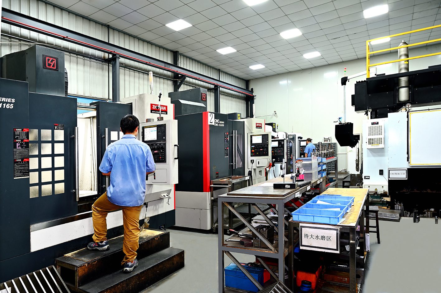
INSIDE THE PLANT
Clad Metal Stamping Lines, Tool Room and Inspection Floor
Real equipment and inspection floor from our Dongguan plant — 25–110T high-speed presses, in-house tool room, and a CMM lab running first-article inspection on every program.
WHERE CLAD GOES WRONG
What Makes Clad Metal Harder to Stamp Than It Looks
Clad strip fails at the interface, not at the outline. These are the four failure modes we design out before the first production coil: bond orientation, exposed core on a sheared edge, inlay drift and two springbacks fighting in one die.
01
The bond line lands in tension
The Challenge
A clad strip bends happily until the interface sits on the outside of the radius, where the two metals try to elongate by different amounts. Nothing shows at try-out. The interface opens slowly under thermal cycling and the part fails as a delamination complaint years into a program, with die and drawing both officially correct.
Our Solution
Bond orientation is checked against every bend at DFM, and where the interface has to cross a bend the radius is opened up or the cladding is moved to the compression side. Roll-bonded and explosively welded strip are not interchangeable here; the bond type is named on the purchase order and verified on first-article sections.
02
Sheared edges expose the core
The Challenge
Every pierce and blank cuts through the cladding and leaves bare core metal on the edge. On a copper-aluminum part that edge is a galvanic couple sitting in humidity; on a silver inlay it is a corrosion path beside the contact face. Drawings rarely mention the cut edge, and it is where field failures start.
Our Solution
Edge exposure is a DFM question, not a surprise: the drawing is asked which edges may show core metal and whether a post-stamp tin or anti-tarnish is allowed. Where the edge has to stay covered, layer ratio and blank layout are set so the cladding wraps the sheared face instead of ending on it.
03
Inlay position drifts against the pilot
The Challenge
An inlay is a fraction of the carrier width, and a few tenths of misalignment puts precious metal under the punch instead of on the contact dome. Coil camber, feed pitch error and strip width tolerance stack into that error, and the die cannot correct what the coil delivers, because the inlay is bonded before it reaches us.
Our Solution
Inlay position tolerance is called out on the strip purchase spec, not only on the part drawing, and the die is piloted off the cladding edge where inlay position is the critical feature. Incoming coil is checked for camber and inlay offset before the first run, and CCD watches the inlay-to-form relationship in production.
04
Two springbacks, one die
The Challenge
Copper, steel, nickel and aluminum do not spring back alike, so a clad part releases as a compromise between two materials, while the soft cladding galls against the tool and the hard core wears the punch edge. Coining the stack to force one shape is the usual shortcut, and it thins the cladding exactly where it matters most.
Our Solution
Bend compensation is set from the actual clad combination and its layer ratio, and angles are proven on the production coil rather than a sample of the carrier alone. Cladding faces that touch the tool get polished inserts and a lubricant matched to the softer metal; forming stations are pulled and polished on counted strokes.
HOW WE STAMP IT
What We Hold in Production
The values we quote and inspect against on clad work: strip thickness, positional and formed tolerance, press capability, inlay alignment and bond verification, all measured on production coil rather than a sample.
Specification Parameter
What We Hold
How It Is Controlled
Strip thickness
0.05–3.0 mm
Coil certificate plus in-process thickness check
Positional tolerance
±0.005 mm piloted · ±0.01 mm formed
First-article CMM at 0.001 mm resolution
Stamping speed
up to 300 SPM
Press matched to part and strip, not to the calendar
Press fleet
21 presses, 25–110 tons
Thin inlay contacts on high-speed frames, heavy sandwich strip on larger presses
Dies
100% designed and built in-house
30 machining machines behind the tool room
Quality system
IATF 16949:2016 · ISO 9001:2015 · ISO 14001:2015
PPAP, mill certificates, lot traceability
Inspection
20 inspection stations
CMM, optical and profile, in-line CCD on inlay position
Cladding and bond
Inlay, overlay or full cladding per drawing
Section and shear check on the interface at first article
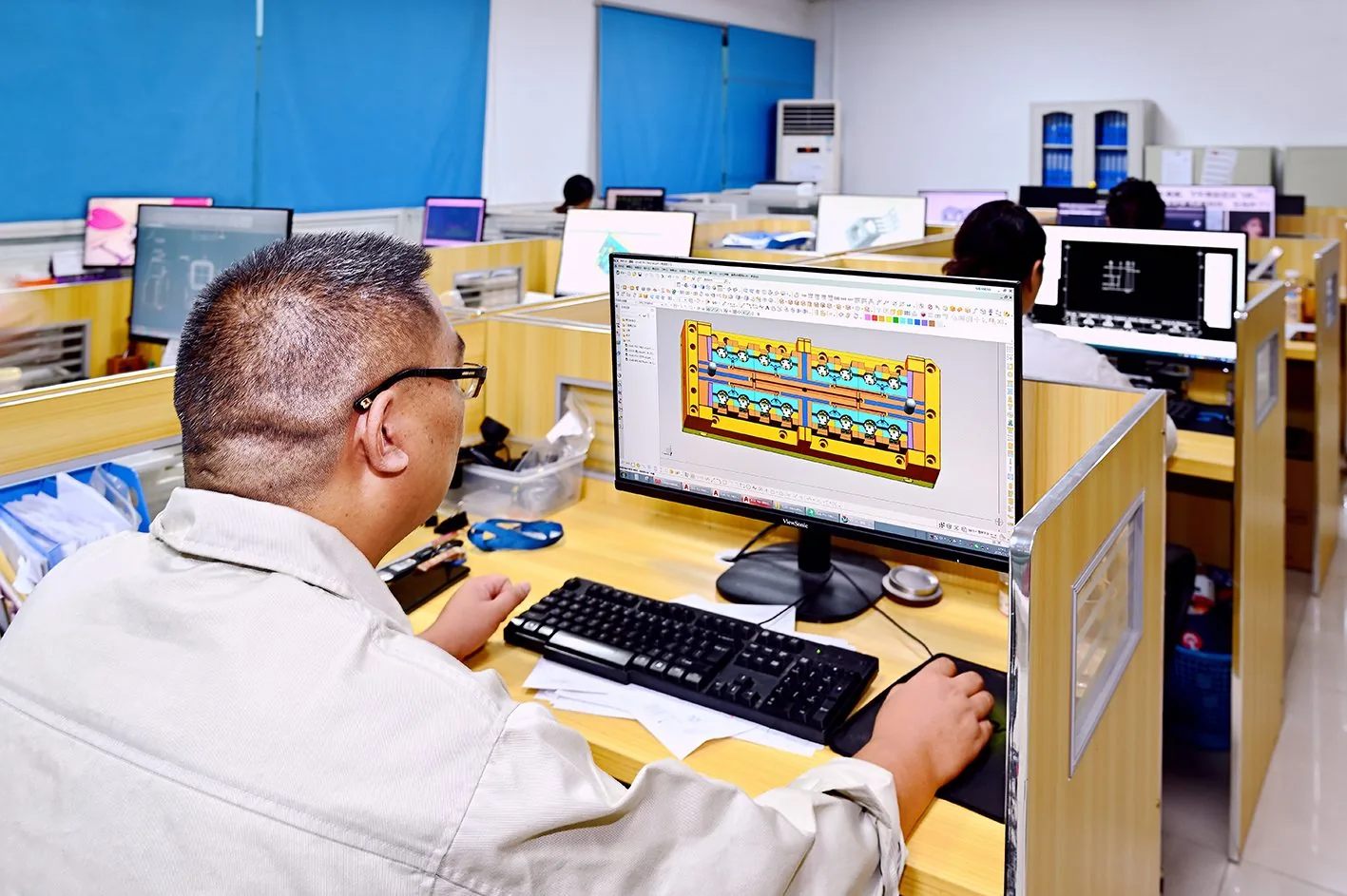
TOOL ROOM
Die design and build
Progressive die design, machining and assembly under one roof, with 30 machining machines behind it: the place bend compensation, inlay piloting and tool polishing are actually decided.
PRESSES
21 presses, 25–110 tons
Thin inlay contacts on the high-speed frames at up to 300 SPM; copper-steel sandwich and Cu-Al transition strip on the larger presses where tonnage has to cover the harder core.
INSPECTION
CMM, optical and CCD
20 inspection stations: first-article CMM at 0.001 mm, optical and profile for edges and radii, in-line CCD watching inlay position against the forming stations.
CLAD SOURCING
Bond type and layer ratio
Roll-bonded, explosively welded, inlay and overlay strip procured against a written construction spec, with mill certificates and bond test reports kept on file.
From Drawing to Production
01
DFM review
Bond type, layer ratio, which face carries the cladding, bend direction against the interface and the finish route settled before a die is cut.
02
Die build
Progressive layout piloted off the cladding edge, forming stations sequenced so the interface is not drawn over a tight radius; die machined and assembled in our tool room.
03
Try-out and first article
Run on the production clad coil, bond sections and formed angles measured on the CMM, shear check on the interface, PPAP documentation raised.
04
Production and SPC
Counted-stroke tool maintenance, in-line CCD on inlay position, SPC on the dimensions and angles the drawing controls.
STRIP AND SUPPLY
Clad Strip: Bond Type, Layer Ratio and Supply
We stamp clad strip; we do not bond or sell it. Tell us the two metals, the bond type and the layer ratio, and we quote strip plus conversion, or stamp coil you supply.
Bond type is a process choice
Roll-bonded strip is the workhorse for copper-aluminum and copper-steel: continuous, uniform layer ratio, built for long runs. Explosive welding covers combinations roll bonding cannot join. The two behave differently at a bend, so bond type belongs on the drawing, not in a general note.
Inlay, overlay or full cladding
An inlay puts precious metal in a narrow stripe, an overlay covers the full width on one face, and full cladding covers the whole strip. Inlay spends the least silver but needs the tightest position tolerance; overlay is easier to pilot and wastes metal across the part width.
You supply or we procure
Either you send clad coil to your own construction spec, or we procure the metals, layer ratio, width and temper you name and quote material plus conversion, with mill certificate and bond report on file. If the construction is still open, we recommend before tooling.
Eight things to settle on a clad drawing before tooling: the ones that decide whether the bond survives the bend and the precious metal lands where it is actually needed.
Bend direction: call out which way the part bends relative to the bond interface — an interface on the outside of the radius is where delamination starts.
Minimum radius: give the radius per clad combination, not one number for the part. A soft aluminum cladding cracks at a radius the copper core would survive.
Inlay position: state inlay centre and width tolerance from a datum the die can pilot from, which means the cladding edge rather than the strip edge.
Which face carries the metal: say whether the silver or nickel face is the contact face or the tool face; it decides stripper side, polish and feed orientation.
Cut edges: state whether exposed core is acceptable at pierce and blank edges, or whether a tin dip, anti-tarnish or wrap-over cladding is required.
Layer ratio: put nominal cladding percentage and its tolerance on the drawing; the same total thickness at a different ratio is a different part.
Coining and embossing: avoid coining across the interface; thinning the cladding at a contact dome is the fastest way to lose the wear life the inlay was bought for.
Finish route: if the clad face is already the finish, do not add post-plating over it — masking a precious-metal inlay costs more than the inlay itself.
How to Order Clad Metal Stampings & Frequently Asked Questions
From drawing to delivered parts: a four-step path with engineering review at the front and 100% dimensional inspection at the back — then the questions buyers ask us most.
Step 1
Submit CAD & Specs
Send 2D/3D drawings (STEP, DWG, PDF) with quantity, material, and tolerance requirements.
Step 2
DFM Feedback & Quotation
Our engineering team conducts DFM analysis and follows up with a competitive quote after the review.
Step 3
Precision Manufacturing
High-speed progressive die stamping, secondary forming, finishing, and surface treatment per your specifications.
Step 4
100% QC & Express Shipping
100% dimensional inspection, anti-corrosion packaging, and global express delivery.
01
Do you supply the clad strip, or do we?
Either. We are a stamper, not a laminator: we do not bond or sell strip. You can send clad coil to your own construction spec, or we procure the metals, layer ratio and width you name and quote material plus conversion.
02
Which clad combinations do you run?
Copper-aluminum, silver-copper, nickel-copper, nickel-steel and copper-steel-copper are the constructions we see most. Send base grades and layer ratio; if the combination is unusual we confirm bond availability before quoting.
03
What is the thinnest clad strip you can stamp?
0.05 mm at the thin end, 3.0 mm at the heavy end. Very thin clad strip is limited by the strip supplier more than the press, because a thin carrier cannot hold a heavy layer without the ratio drifting.
04
Will the cladding delaminate when you bend it?
Not if the interface is oriented against the bend and the radius suits the combination. Delamination comes from an interface on the outside fibre, a radius below what the cladding allows, or a bond type picked on cost. All three are checked at DFM.
05
Clad strip, pre-plated strip or post-stamping plating?
Pre-plated strip is plated all over before stamping. Clad strip has the precious metal roll-bonded in as a layer, metallurgical rather than electroplated, and it can be a stripe on one face. Post-stamping plating is selective plating on the finished part.
06
What tolerance do you hold on a clad part?
±0.005 mm on piloted positional features, ±0.01 mm on formed features, both verified on the CMM at first article. Inlay position depends on the strip supplier, so that tolerance is agreed on the coil spec as well.
Ready to Start Your Precision Stamping Program?
Send your drawing today — engineering runs a free DFM review and detailed pricing follows the review.
100% Confidential | NDA Protected | 24H Response
We use cookies to understand how visitors use our site and to improve it. Choose what's fine with you — you can change your mind anytime.Cookie Policy